Reminder of the steps necessary for the smooth progress of engraving production. #
This tutorial will cover everything needed to produce your first engraving on your machine.
We will divide this tutorial into different steps:
- Preparation of your SVG
- Using Inkscape
- Managing speed by color
- Managing power by opacity
- Vector drawing, best practices
- CASE STUDY: Vectorization
- Creating your .ngc file
- Via the terminal
- Via graphical interface
- Preparing your file via the Plugin
1.1 Prepare your SVG #
For this documentation, we will be using the open-source software Inkscape. There are other vector drawing software options available, such as Illustrator.
1.2 Managing Speed by Color #
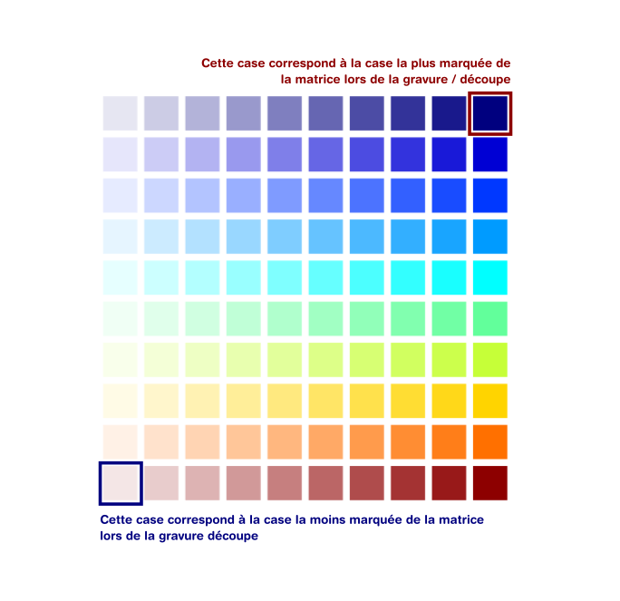
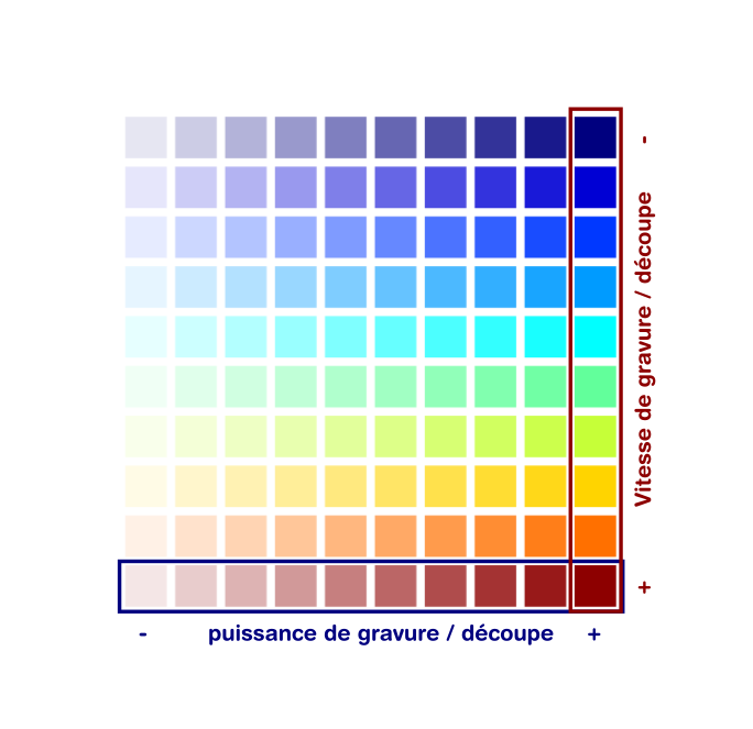
- Red represents the fastest speed for engraving and cutting (last row of the matrix). Red indicates that you have chosen to apply 100% of the speed specified in the .ngc preparation settings.
- Blue represents the slowest speed for engraving and cutting (first row of the matrix). Blue indicates that you have chosen to apply 10% of the speed specified in the .ngc preparation settings.
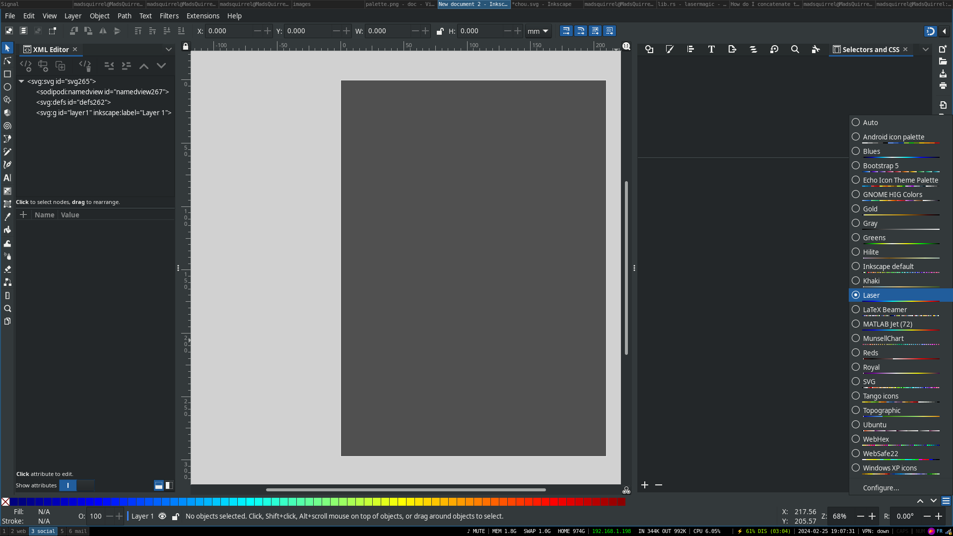
1.3 Managing Power by Opacity #
- 100% opacity will be expressed as 100% of the power specified in the .ngc preparation settings (right column).
- 10% opacity will be expressed as 10% of the power specified in the .ngc preparation settings (left column).
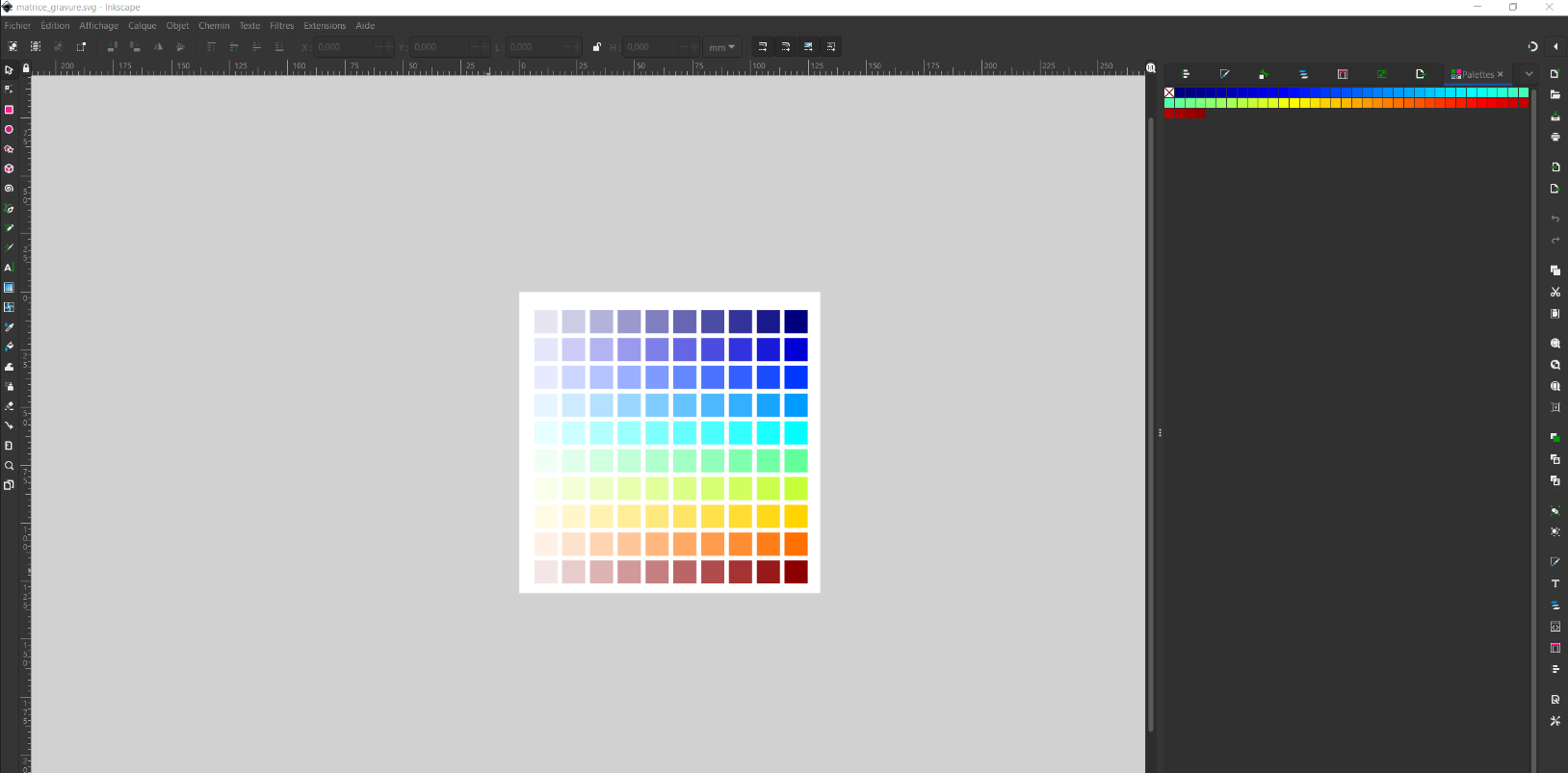
The color palette is called “Laser,” and you can install it by running the following in the plugins folder:
- For Windows: MakeFile.bat
- For Linux: make install
It’s imperative to use colors from this range; otherwise, the path will not be considered when creating the .ngc file, which is used by the laser.
1.4 Drawing #
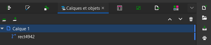
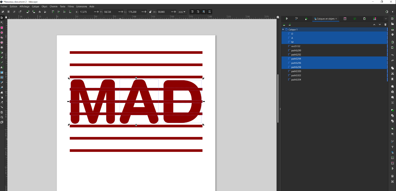
Your shapes/drawing must consist only of “Paths.”
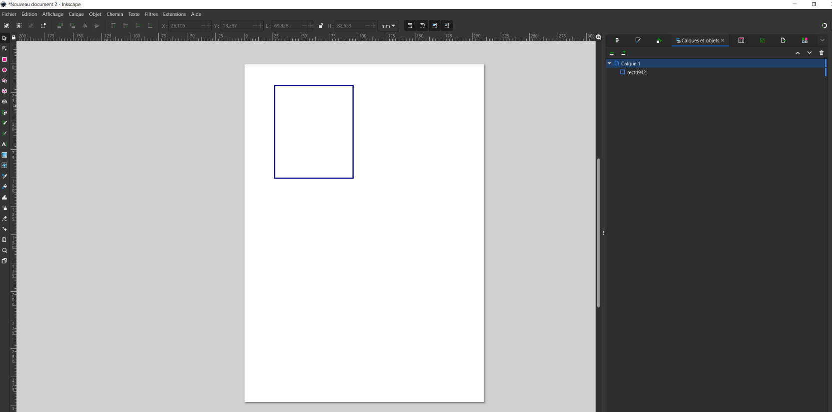
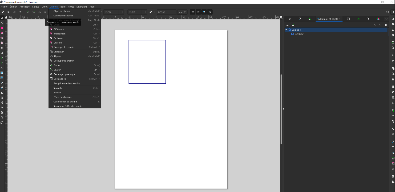
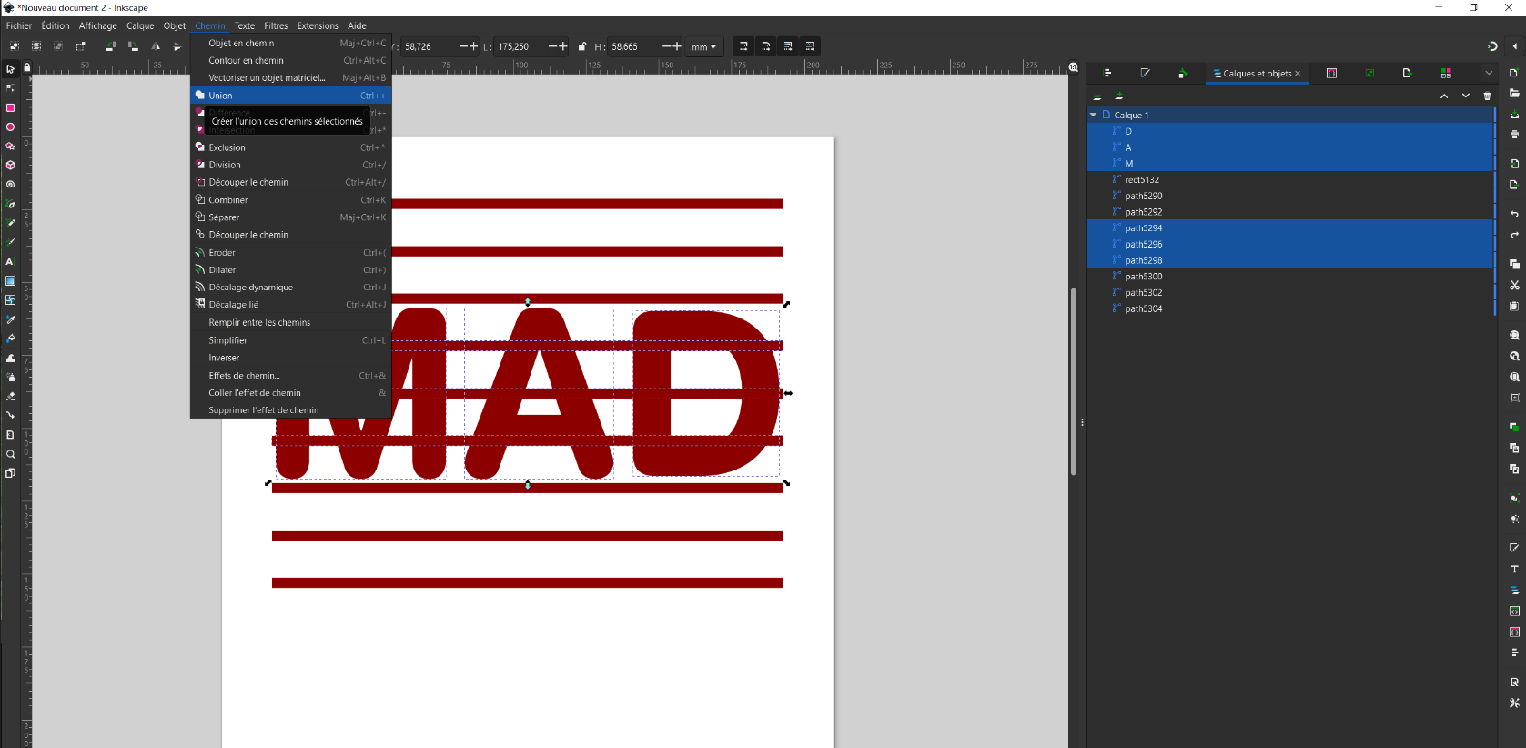
When creating your drawings, remember to simplify and make them as clean as possible (fewest independent “paths” possible). A simple tip for this is to use the “Union” option in the “Path” menu to remove all intersecting paths, preventing the laser from passing over the same spot multiple times.
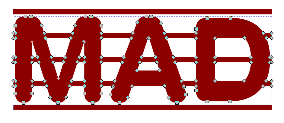
If the elements don’t touch, they should remain as independent paths in your drawing. If you use the “Union” function to make them into a single path, the slicer may have problems calculating the path to take, making the process longer. Use the “Split path” option in the path menu to extract paths that do not touch.
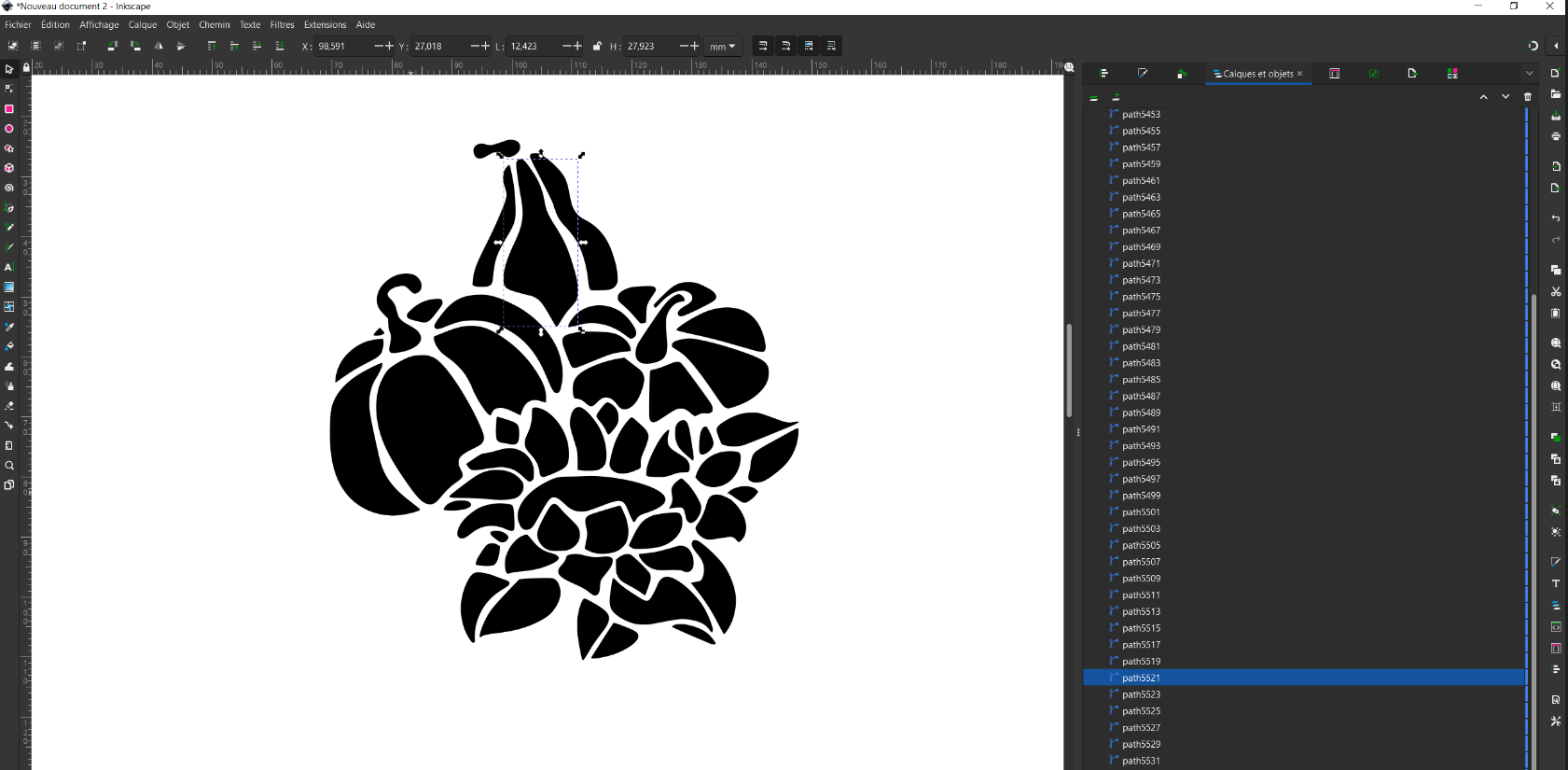
1.5 Case Study: Vectorization #
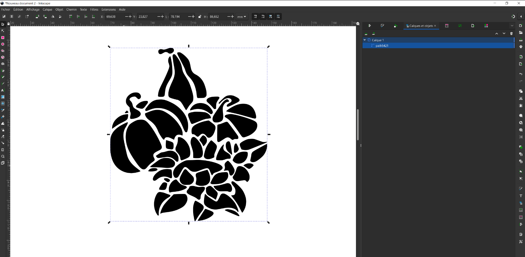
After vectorizing your image, the different parts of your image are combined into a single path. However, as mentioned earlier, when our shapes are separate, for the sake of efficient path calculation, it’s better for each shape to be an independent path.
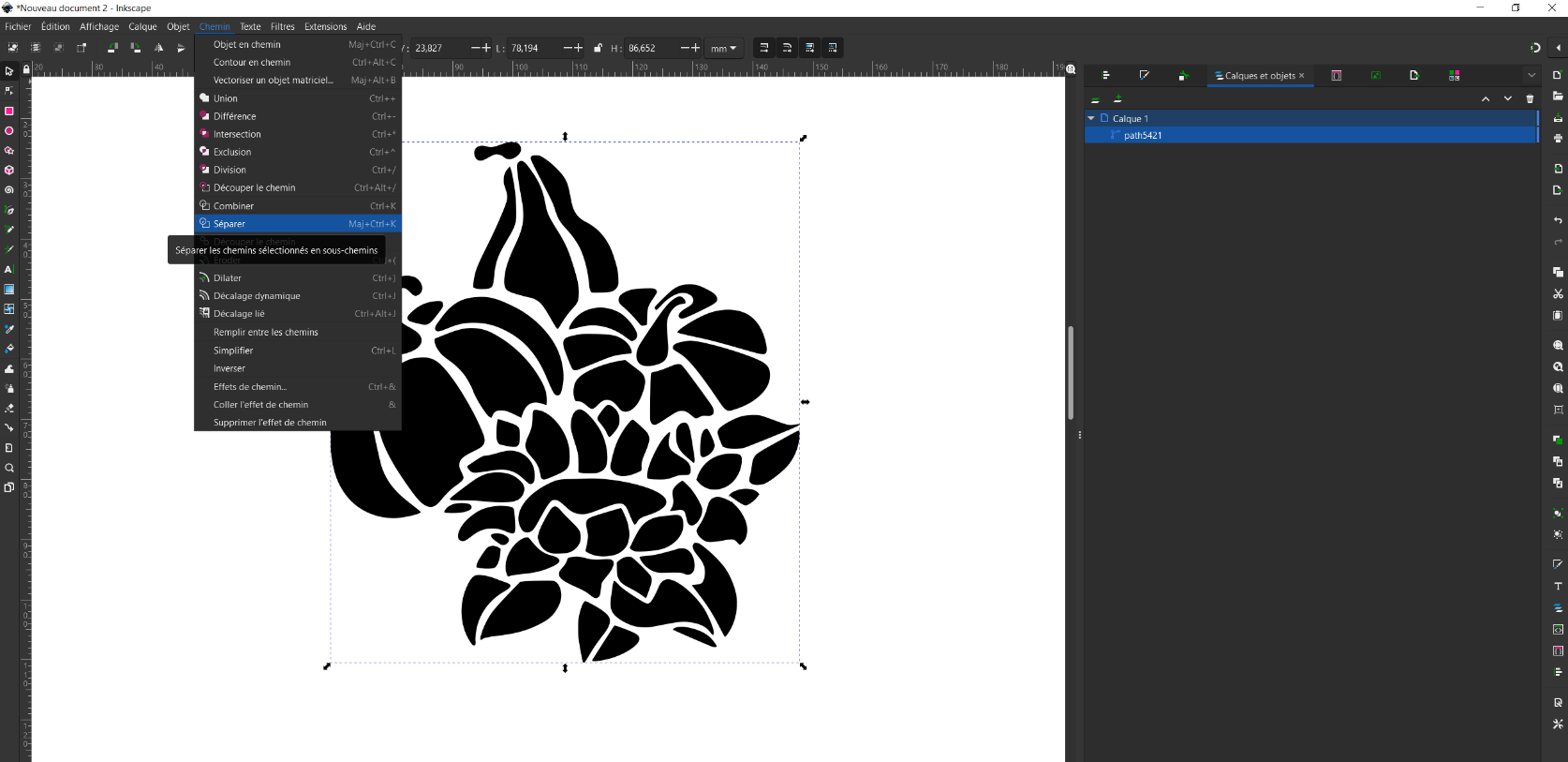
Path > split
1.6 Error Case #
1.6.1 Incorrect Color #
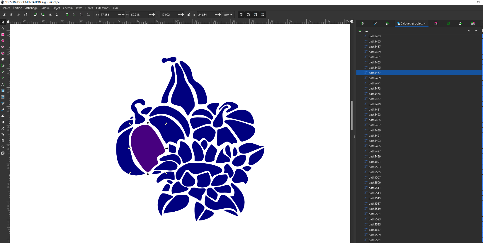
If the color you’ve chosen isn’t in the “Laser” color range, you’ll receive an error message on that path when converting to .ngc with Magic Laser.
To display warnings:
On Windows:
set RUST_LOG=warn
On Linux:
export RUST_LOG=warn
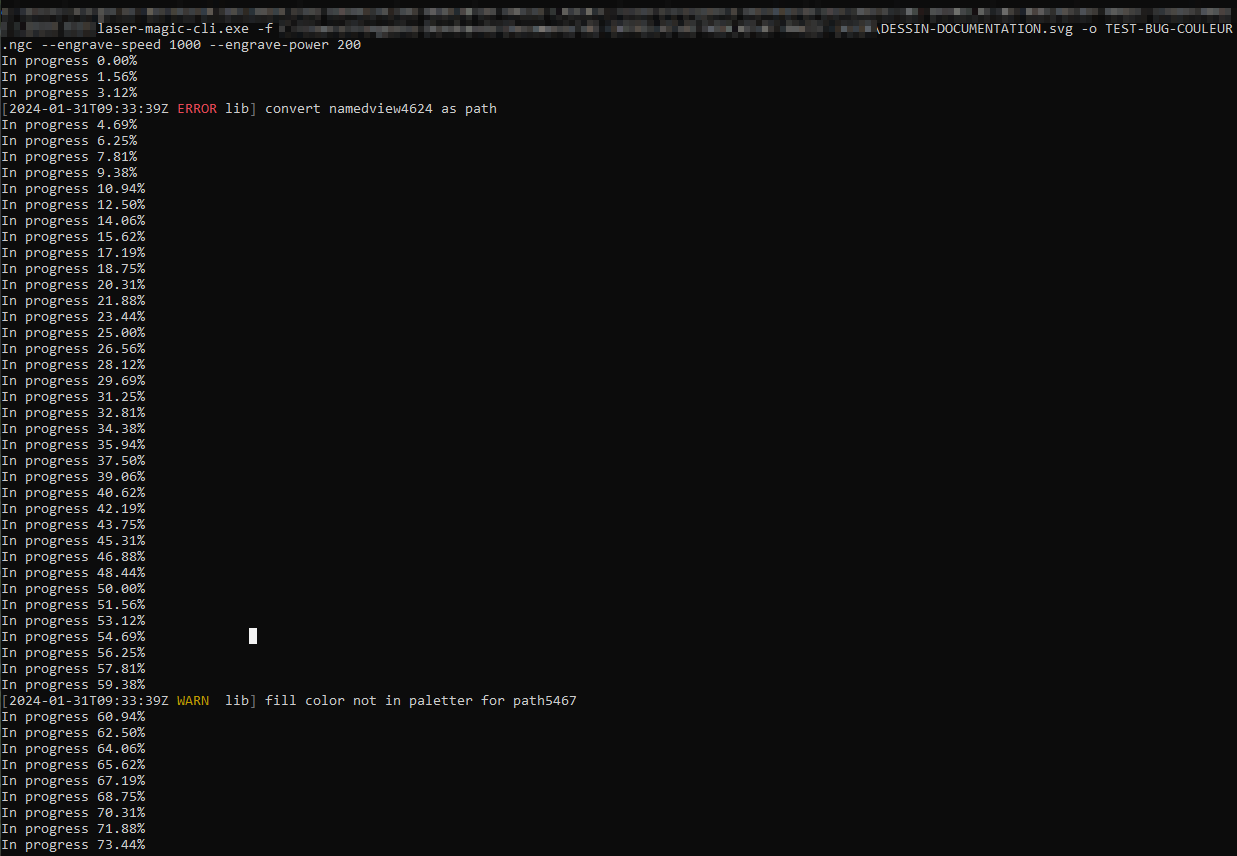
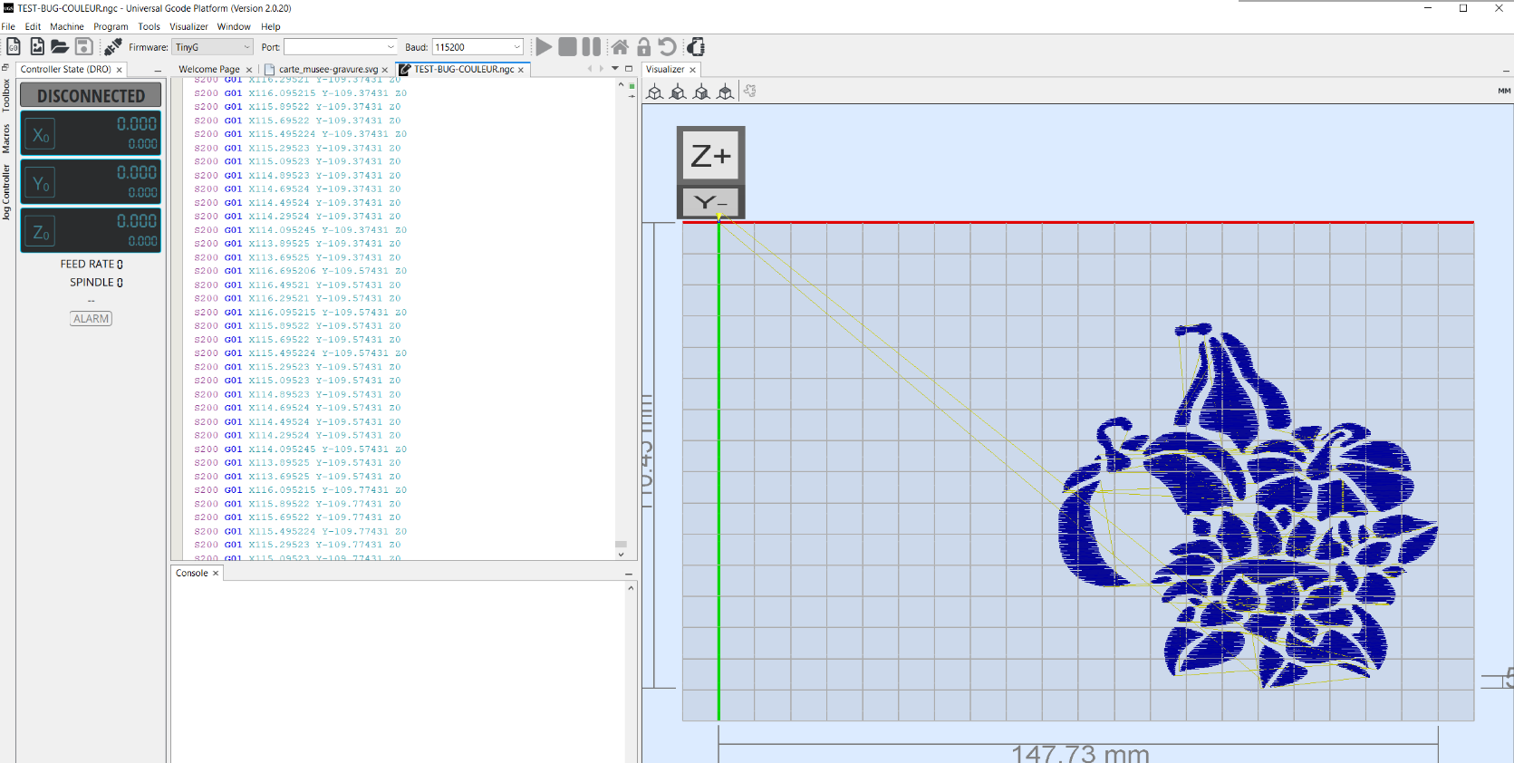
The path with the wrong color won’t be processed and won’t appear in UGS.